Why modular robots?
Flexible configuration options - better adaptation to application needs
Modules can be combined in various configurations to adapt the kinematic system to the application needs. The use of a standard robot is not always necessary. Sometimes 3 or 4 appropriately configured axes are enough to operate a process.
Ready-to-use positioning system that meets all CE standards
The modules can be delivered as a ready-made kinematic system equipped with a full control system including Teach Pendant. As well as a ready-made industrial or collaborative robot, in this case they are a separate part of the device that meets the necessary CE and safety standards (built-in SAFETY PLC).
Quick startup
The finished system can be easily and quickly integrated into the rest of the production line. The robot work program is created using Teach Pendant, which makes commissioning simple and does not require knowledge of complex drive motion programming procedures.
Easy to upgrade or rebuild in the future
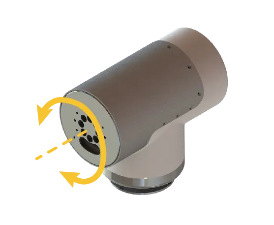
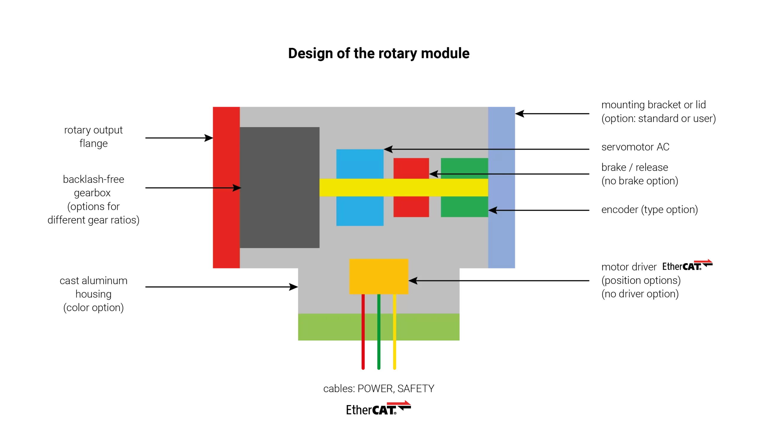
Each module is a separate unit, inside which the motor and gearbox are placed. The modules can be equipped with a brake, driver and other accessories. They can be connected to a pre-prepared control system. This approach makes it possible to rebuild the manipulator and use individual parts in other applications.
Cooperation with various control systems
The modules can work with any control system that allows communication via EtherCAT.
Adapted to Industry 4.0 standards
The digital twins of the module system are available in the SIMULTUS simulation software we provide, where you can experiment with their different configurations. The control program can be created in simulation, and the finished and tested one can be copied to the device. The system also works with OmniMES System for machine monitoring and production management.
Examples of modular robots applications
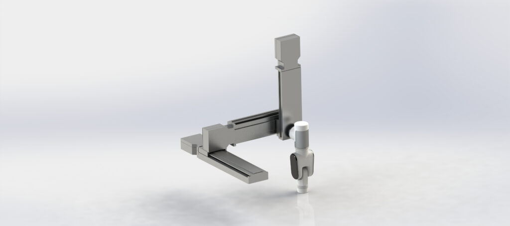
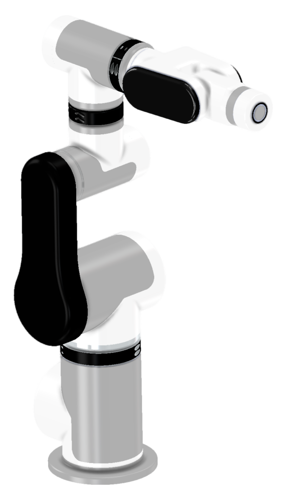
Modular robots system
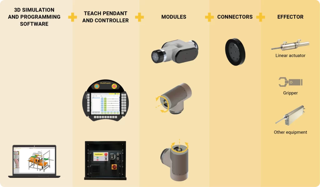
Selection of modular robot options
I need individual modules
In our offer there are available standard modules. They can be adapted to your application by selecting different options for their manufacture.
You can check the list of available options on the designation code page. Ask our specialists to help you select modules suitable for your application.
I need a standard ready-made set
The palette of our standard kits is constantly expanding. It includes robots from 2 to 6 axes with ready-made control system and TeachPendant. The kits meet CE standards and are equipped with appropriate safety systems like SafetyPLC.
I need a customized set
We supply ready-to-run, safety-compliant kinematic systems prepared according to your specifications. They can be equipped with a control system and TeachPendant.
Please contact our technical support for details.
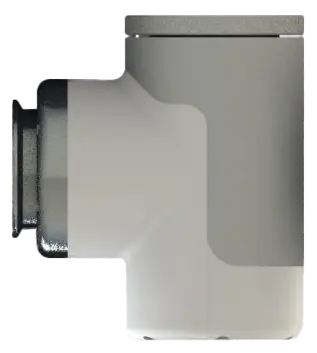
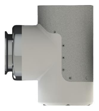
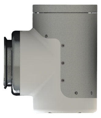
Design of the rotary module
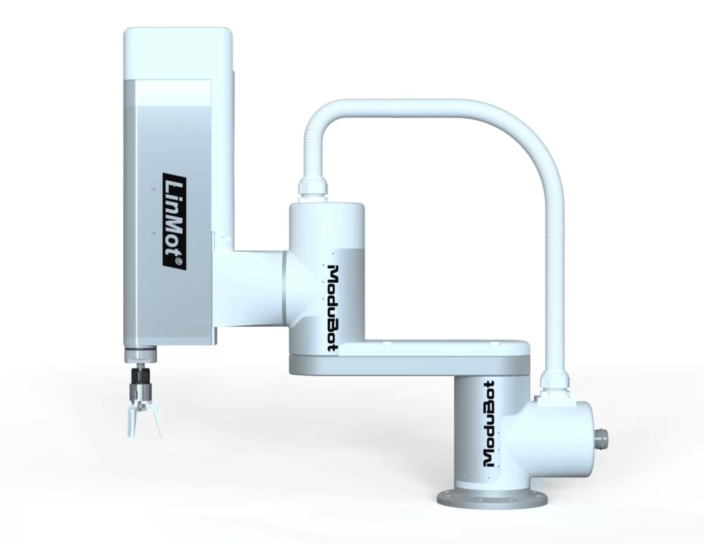
This is not a typical SCARA robot
This is not a typical SCARA robot. By using the LINMOT PR02 direct linear-rotary drive and connecting it to the Modubot modular robot, we get a device that works similarly to a SCARA robot.
Combining the linear drive with the modular robot allows for controlling the two end axes with very high speed and precision while maintaining force and torque control. This design is perfect for applications such as tightening nuts or screwing screws.
Contact us for details about this product – form at the bottom of the page.
Specification - 1-axis rotary modules
Basic models and technical parameters

| Rotating modules | MR-R1 | MR-R2 | MR-R3 | MR-R4 | MR-R5 |
|---|---|---|---|---|---|
| Housing | S 110 | S 110 | S 110 | S 115 | S 130 |
| Gearbox ratio | 50 | 80 | 100 | 5 | 80 |
| Rated torque [Nm] | 14,5 | 23,2 | 29 | 33 | 52,8 |
| Rated speed [°/s]. | 420 | 260 | 216 | 316 | 198 |
| Max speed [°/s] | 420 | 260 | 216 | 420 | 265 |
| Rotating modules | MR-R6 | MR-R7 | MR-R8 | MR-R9 |
|---|---|---|---|---|
| Housing | S 130 | S 130 | S 130 | S 169 |
| Gearbox ratio | 120 | 50 | 80 | 120 |
| Rated torque [Nm] | 79,2 | 54 | 86,4 | 129,6 |
| Rated speed [°/s]. | 132 | 415 | 259 | 173 |
| Max speed [°/s] | 175 | 420 | 263 | 175 |
The table shows the parameters of standard modules MR-R1~MR-R9. Modules with other parameters are also available (see table Designation Codes). Please contact our technical support for details and available options.
Specification - 2-axis rotary module (wrist)

2-axis rotary module (wrist) - basic technical parameters
| Wrist K1 | Wrist K2 | Wrist K3 | ||||
|---|---|---|---|---|---|---|
| axis 1 | axis 2 | axis 1 | axis 2 | axis 1 | axis 2 | |
| Rated torque [Nm] | 13,3 | 8 | 21,28 | 12,8 | 26,6 | 16 |
| Rated rotary speed [deg./s] | 216 | 360 | 135 | 225 | 108 | 180 |
| Max speed [deg./s] | 432 | 540 | 270 | 337,5 | 216 | 270 |
| Motor power [W] | 100 | 50 | 100 | 50 | 100 | 50 |
| Gearbox ratio [-] | 50 | 50 | 80 | 80 | 100 | 100 |
| Motion range [deg] | +/- 90 | no limit | +/- 90 | no limit | +/- 90 | no limit |
Position and type of mounting flanges
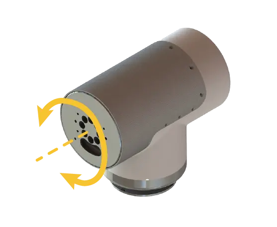

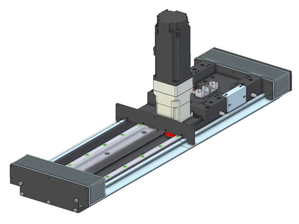
Depending on the design of the kinematic chain, the modules can have a mounting flange (green color) mounted in line with the motor axis (type F0) or at 90 degrees (type F90). The flange can be standard or made to the user’s order.
Position of the servo motor driver


Regardless of the position and type of mounting flange, the position of the servo motor driver can be selected. Optionally, the module may not have the driver mounted inside the housing. In this case, the driver must be located outside the module.
Examples of cable positioning options

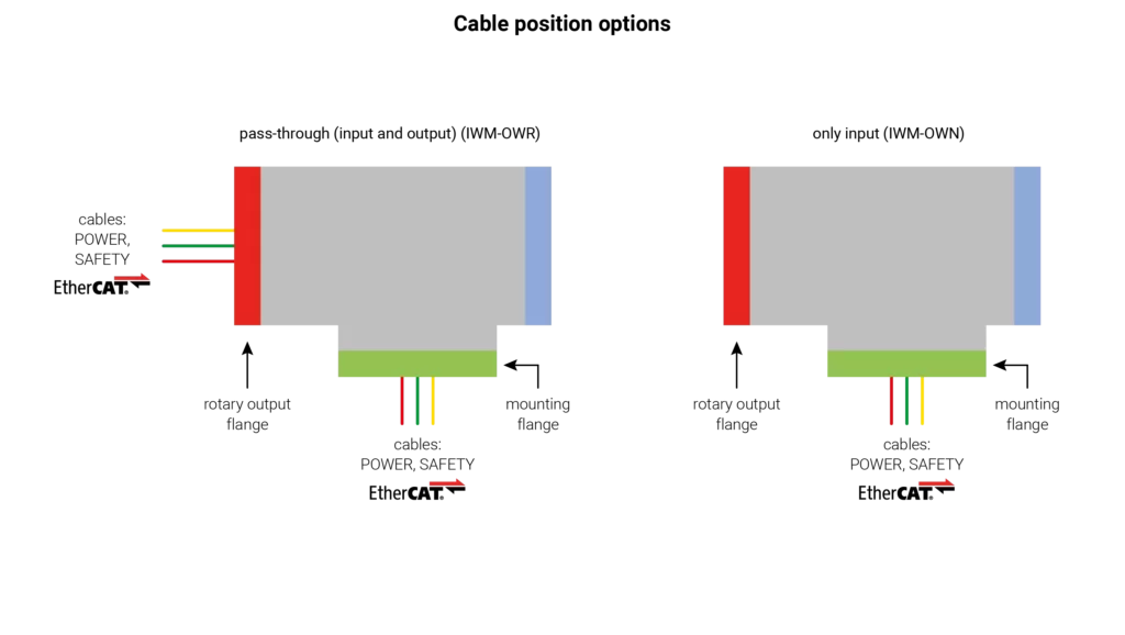
If the module is the center of the kinematic chain, then the wires (input and output) can be brought out from the side of the mounting flange and the output flange. If no other modules are attached to a given module, then the input wires can also be brought out only from the side of the mounting flange. The wires can also be brought out from the lids. Other cable routing options according to the table of marking codes. Please contact our technical support for details and available options.
Remote control (Teach Pendant) of the modular robot
Teach Pendant
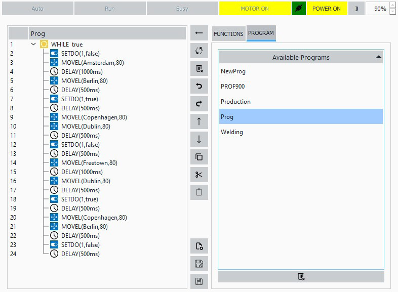
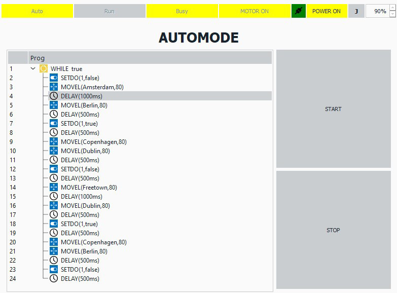
Teach Pendant is used to program the movements of a robot (manipulator). It can be used to create both simple and very advanced robot movement programs. As with standard robots, it allows you to memorize positions and create a program of movements between memorized points, along with transition conditions. It also allows you to control the robot in manual mode. Programming is intuitive and does not require advanced programming knowledge.

Would you like to test this device in 3D?
Modular robot controller
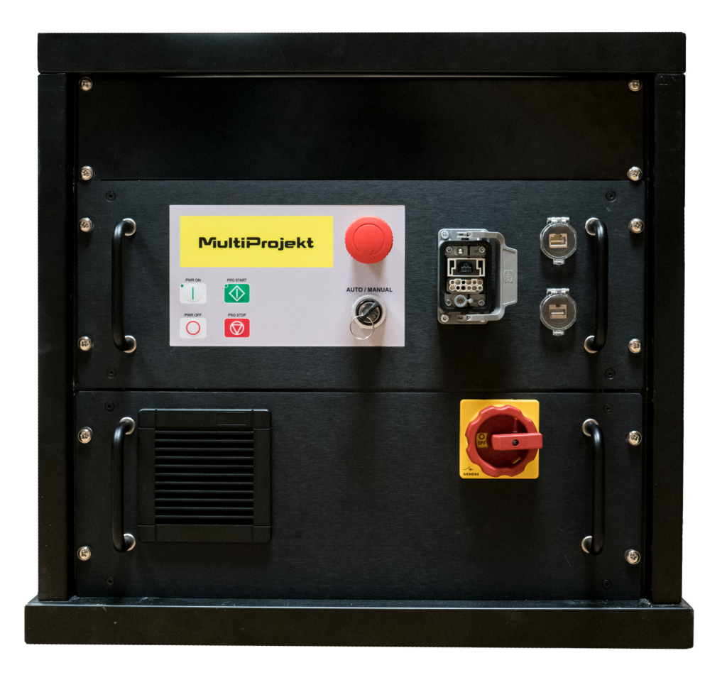
Controller
The finished controller meets all safety requirements related to robots (including built-in SAFETY PLC). Built-in digital I/O. EtherCAT protocol.
Connectors:
- Ethernet
- USB
- modular robot connector
- Teach Pendant connector
- 230V power supply
- digital inputs/outputs (DI/DO)
- analog inputs/outputs (AI/AO)
Buttons and switches:
- E-Stop
- AUTO/MANUAL switch (key)
- main power switch ON/OFF
- START/STOP, POWER ON/OFF buttons


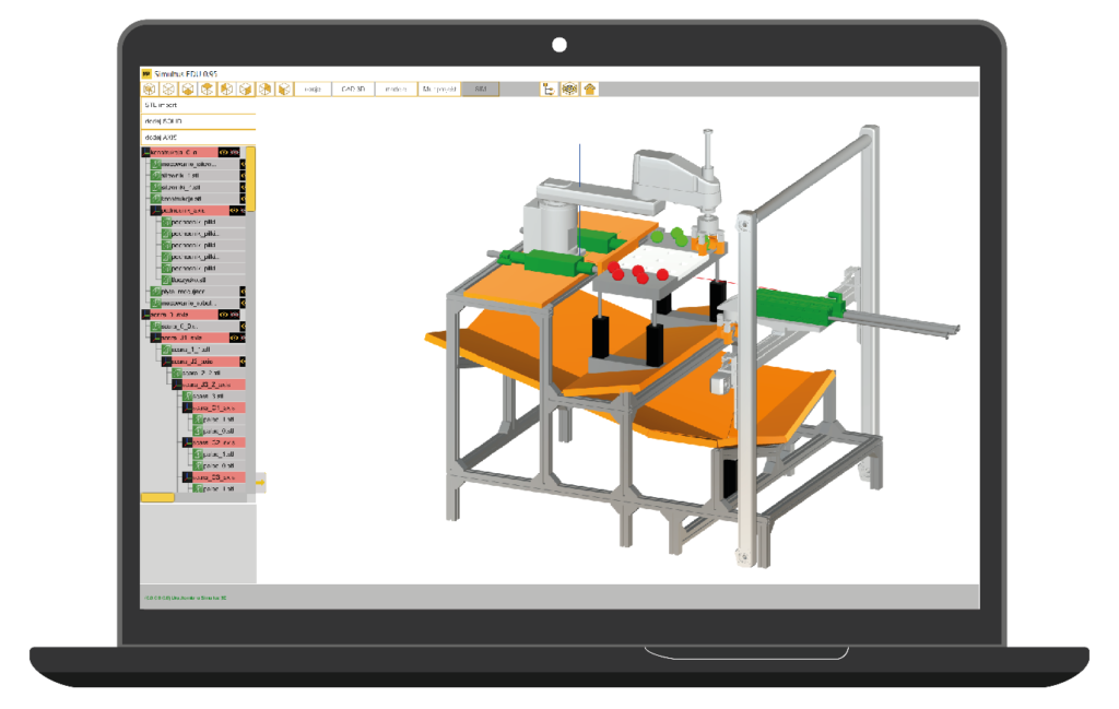
Simultus - 3D tool software
Free PC-based software allows you to test your system in a virtual version in 3D without having to buy hardware (digital twin). Import of 3D solids from CAD programs allows you to test your own manufacturing station. Advanced software allows simulations using solid state physics.

Would you like to test this device in 3D?
Custom-made modular robots
Customized modular robots
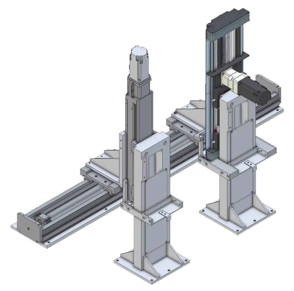
We design, manufacture and supply ready-to-run, safety-compliant application-specific kinematic systems according to customer specifications. Please contact our technical support for details and available options.

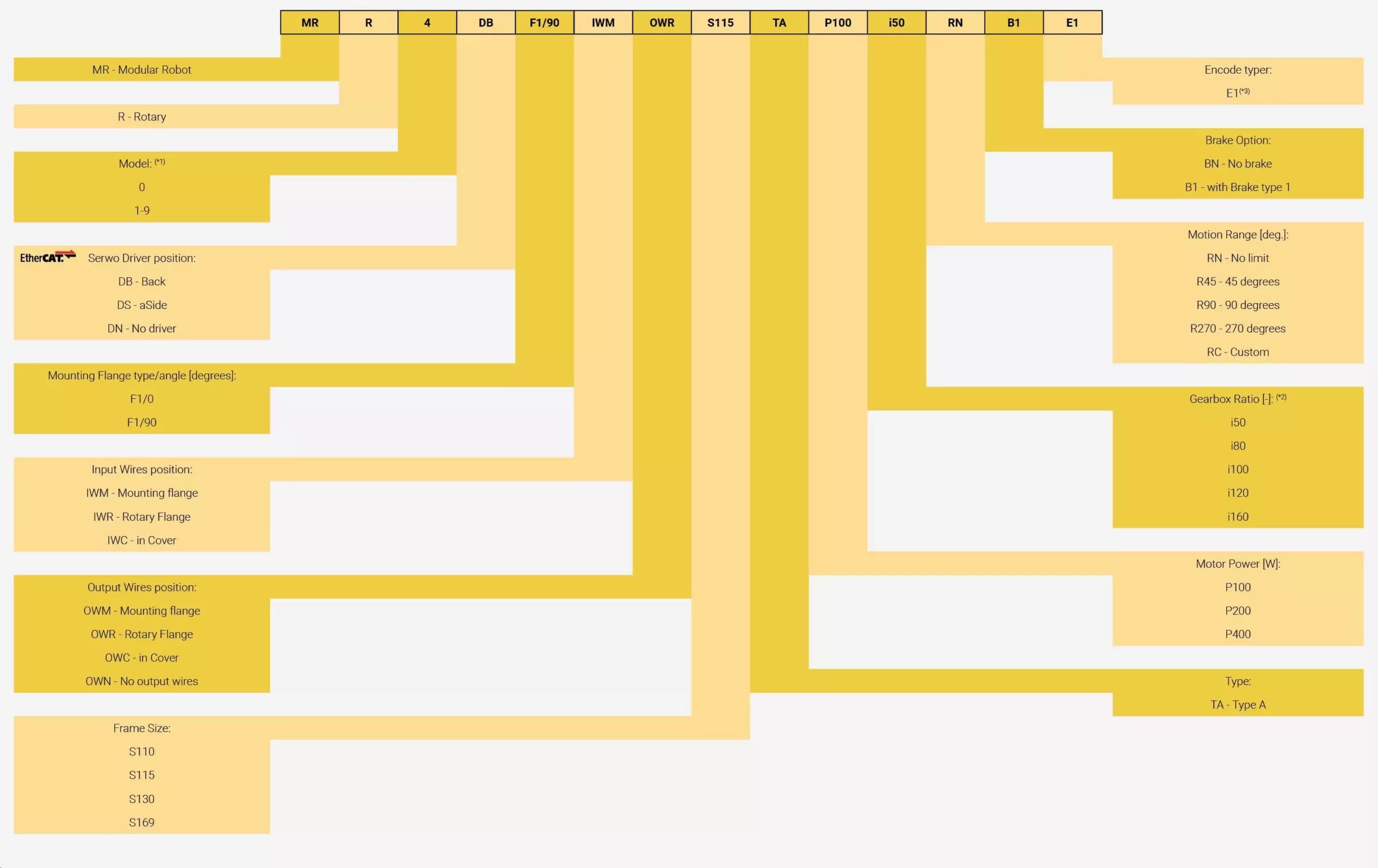
Designation codes - rotary modules

| module frame size | ratio option | gearbox size |
|---|---|---|
| MR-R-S110 | 50, 80, 100, 120 | 17 |
| MR-R-S115 | 50, 80, 100, 120, 160 | 20 |
| MR-R-S130 | 50, 80, 100, 120, 160 | 25 |
| MR-R-S169 | 50, 80, 100, 120, 160 | 32 |
*1 – distinguisher of standard model from 1 to 9, for other options enter ‚0’
*2 – table of possible gear ratios for a specific housing size Sxxx to the right
*3 – Multiturn Absolut Encoder 65536 ppr
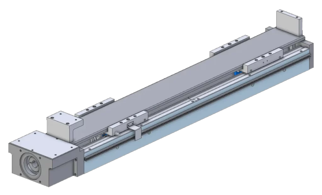
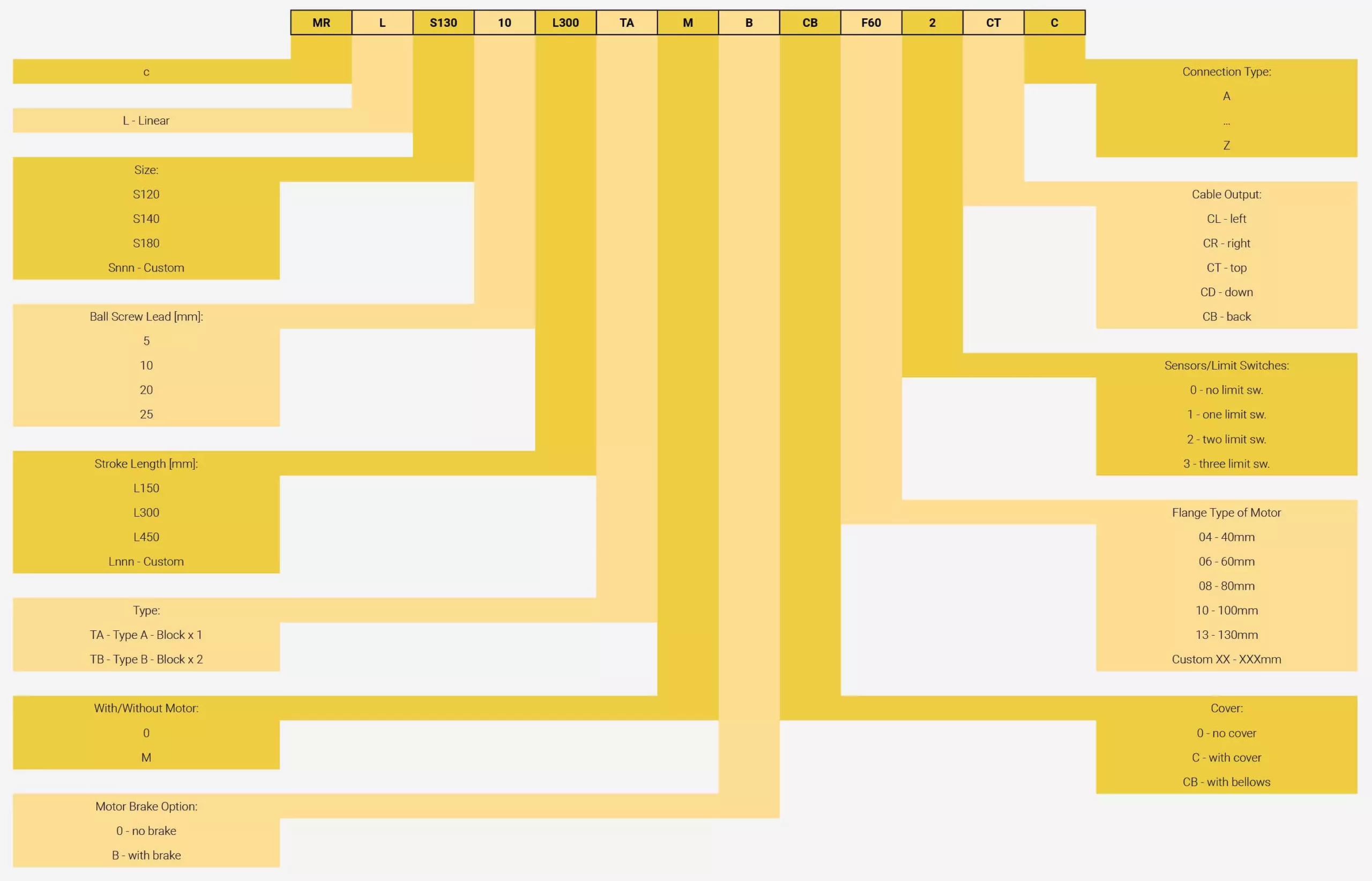
Designation codes - linear modules
Dimensional drawing - MR-R-F1/0-S110
| MR-R-F1/0-S110 | ||
|---|---|---|
| Serwo driver position | DB | DS |
| a1 [mm] | 103 | 44 |
| b [mm] | 112 | 145 |
| b1 [mm] | 8 | 35 |

Dimensional drawing - MR-R-F1/90-S110
| MR-R-F1/90-S110 | ||
|---|---|---|
| Serwo driver position | DB | DS |
| a1 [mm] | 88 | 28 |
| b [mm] 1 | 112 | 145 |
| b1 [mm] | 23 | 50 |

Dimensional drawing - MR-R-F1/0-S115
| MR-R-F1/0-S115 | ||
|---|---|---|
| Serwo driver position | DB | DS |
| a1 [mm] | 108 | 45 |
| b [mm | 117 | 147,5 |
| b1 [mm] | 8 | 55 |

Dimensional drawing - MR-R-F1/90-S115
| MR-R-F1/90-S115 | ||
|---|---|---|
| Serwo driver position | DB | DS |
| a1 [mm | 95 | 30 |
| b [mm] | 117 | 147,5 |
| b1 [mm] | 23 | 55 |
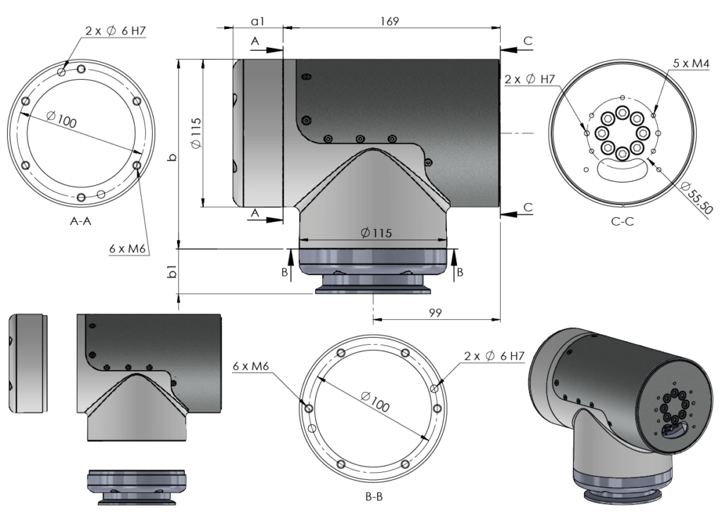
Dimensional drawing - MR-R-F1/0-S130
| MR-R-F1/0-S130 | ||
|---|---|---|
| Serwo driver position | DB | DS |
| a1 [mm] | 88 | 32 |
| b [mm] | 132 | 155 |
| b1 [mm] | 8 | 45 |

Dimensional drawing - MR-R-F1/90-S130
| MR-R-F1/90-S130 | ||
|---|---|---|
| Serwo driver position | DB | DS |
| a1 [mm] | 75 | 18 |
| b [mm] | 132 | 155 |
| b1 [mm] | 23 | 60 |

Dimensional drawing - MR-R-F1/0-S169
| MR-R-F1/0-S169 | ||
|---|---|---|
| Serwo driver position | DB | DS |
| a1 [mm] | 90 | 28 |
| b [mm] | 171 | 189,5 |
| b1 [mm] | 8 | 35 |
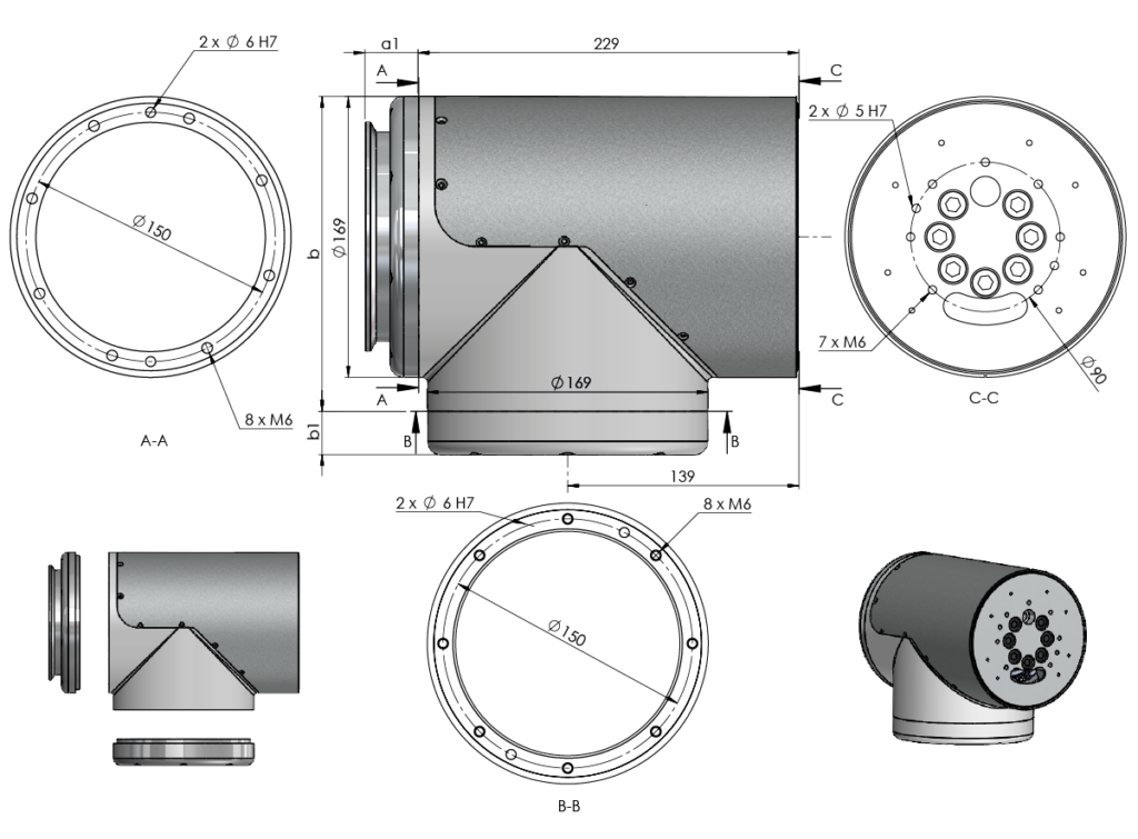
Dimensional drawing - MR-R-F1/90-S169
| MR-R-F1/90-S169 | ||
|---|---|---|
| Serwo driver position | DB | DS |
| a1 [mm] | 75 | 18 |
| b [mm] | 171 | 189,5 |
| b1 [mm] | 23 | 32 |
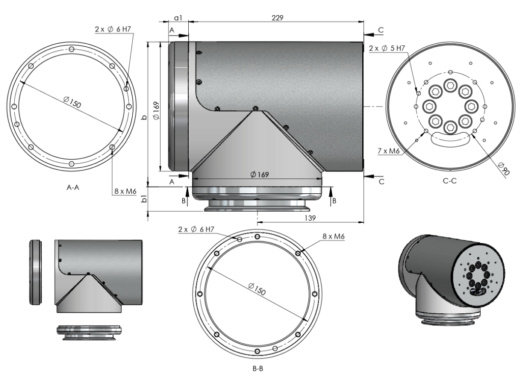
Dimensional drawing - wrist K1


Contact Form

- Pilotów 2E street, 31-462 Kraków
- +48 505 251 486
- info@modubot.pl
- www.multiprojekt.pl


